| Author |
 Topic Topic  |
|
|
tmt
Advanced Member

2766 Posts |
 Posted - 05/26/2009 : 22:21:21 Posted - 05/26/2009 : 22:21:21


|
Here's a photo set for disassembling the P7230, which I had to figure out a few months ago
when mine died unexpectedly. Enjoy!
1) All the tools I needed to dismantle and reassemble it:
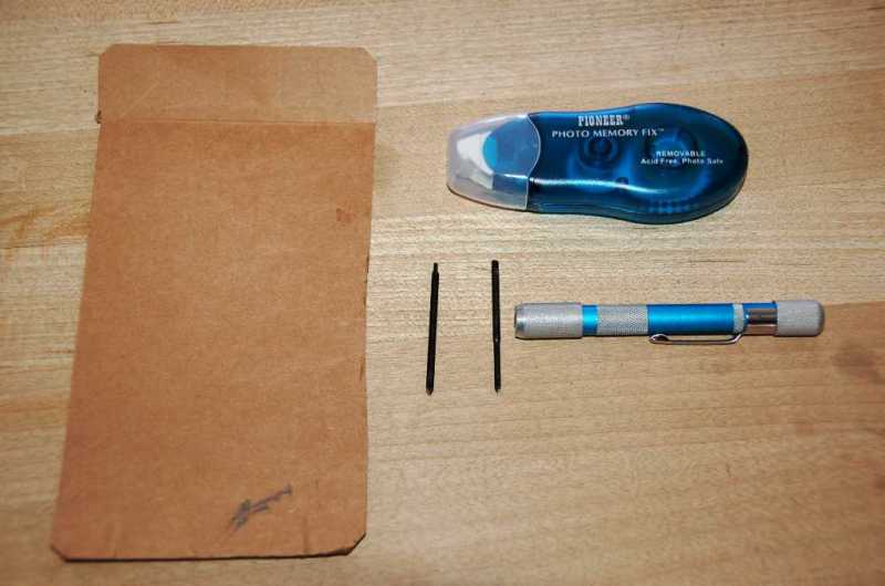
The screwdrivers are a 000 and 0000 Philips, the cardboard is for lifting the keyboard and
made from a cereal box. The tape dispenser is a glue strip applicator with removable glue,
used for photo albums and scrapbooking, I found it in a crafts store. The glue is used to
re-attach the keyboard to the frame on assembly.
2) First thing is to remove the keyboard. Here's a top view of the hold-down strip:

3) More detail on removing the strip:

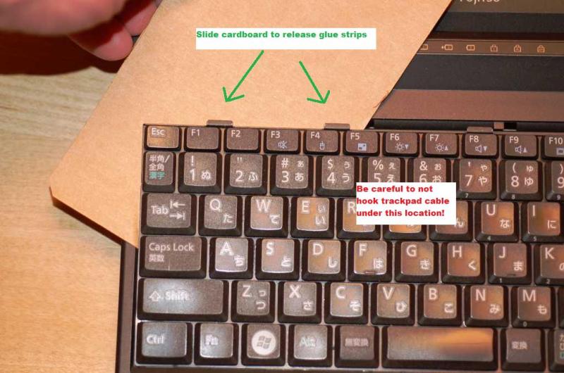
4) The keyboard is glued down to the top frame with double-sided glue strips, in multiple
locations. To break the bonds without bending the very delicate keyboard, I used a piece
of cardboard cut from a cereal box. Inserting it behind the keyboard and driving in at an angle
popped the bonds easily. But, be careful not to hook the flat cable that connects the touchpad
and fingerprint sensor to the motherboard. It's roughly below the T,Y, G and H keys, as you can see
in the following photos.
5) The bezel led indicators and switches are connected by the wide ribbon cable which simply plugs
into a surface connector. To avoid crimping the cable, I wrapped it around a pencil to get the
proper leverage:

6) In all, three connectors must be released from the top cover. The cable I marked [1] is the
indicator/button cable mentioned above, [2] is the connector for the speakers, and [3] is the
touchpad/fingerprint sensor cable.

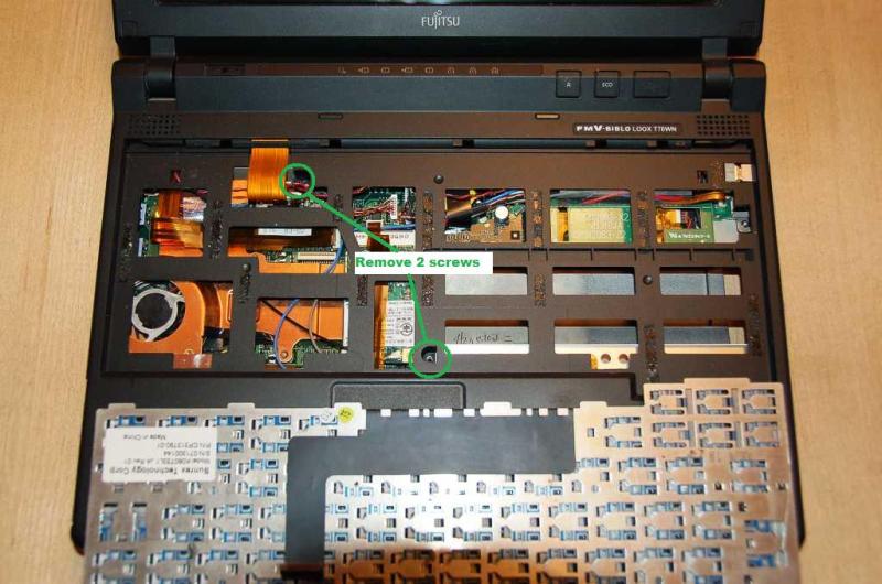
7) Two screws connecting the top and bottom covers must now be removed. This photo also shows the
location of the glue strips holding down the keyboard:
8) Flip the machine over and get out your tiny screwdriver, 15 screws must be removed. There are
three different sizes, so keep them all well-organized! The two screws circled in red don't need
to be removed to open the top cover, they only connect to the hinges.

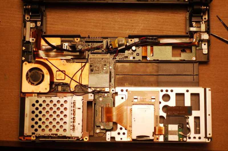
9) The top cover now lifts off easily, revealing the motherboard:
10) Bottom view of the top cover, for reference:
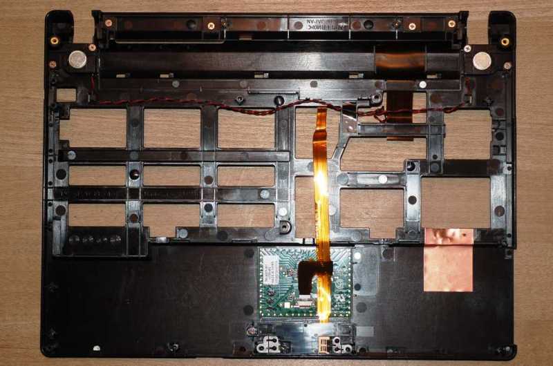
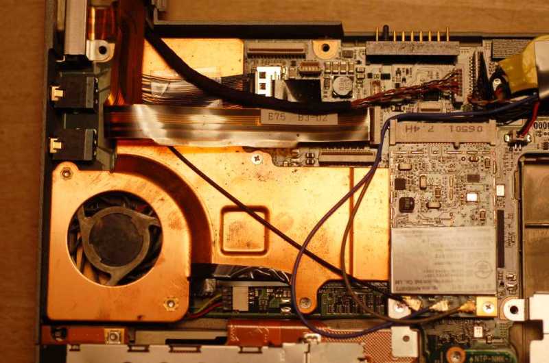
11) Closeup of the motherboard, with heatsink/fan assembly and cables still in place. The mini-pciE
card at the right is my Atheros XSpan wireless card:
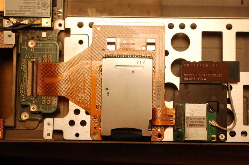
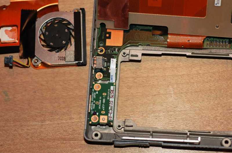
12) The SD card socket and bluetooth are attached to the media bay frame below the right side
palmrest (wireless card visible at top left for orientation):
13) Disconnecting the LCD cable is simple, just pull up on a plastic tab revealing this right-angle
flush connector. The Ethernet cable is the fuzzy multi-pair cable in the foreground, which connects
to an adjacent socket on the MB:

14) The right side of the case is empty by comparison, holding only the RJ11 phone/modem connection
and a USB socket. The green PCB at the bottom of the photo has the modem mounted to the underside.

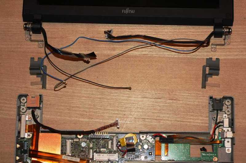
15) Removing the last two screws (circled in red above), allows the screen and base to be separated.
Note the plastic hinge covers, three wireless cables (in my 80211N-equipped machine), LCD cable on the
left and camera/mic connectors on the left.
16) Three screws removed allow the heatsink to come off the motherboard. The thermal compound was badly
cooked and cracked/hardened on the CPU (top), and had the consistency of pigeon poo on the northbridge
(bottom center). I cleaned it off both the copper and the chips, replacing with Arctic Silver 5 on
reassembly. Definitely don't attempt to reuse the factory stuff, it won't re-bond.

17) With the pcmcia socket assembly lifted up, a few more components are visible, including the left-side
USB socket PCB and the hard drive bay:
18) Lifting out the motherboard and other miscellaneous stuff, the bottom cover is pretty simple.
The VGA cable is still in place at top left:

19) Here's the bottom of the motherboard. Note my Japan unit does not have a port replicator nor
TPM device (open pads at top left and bottom center):

20) Here are all the pieces laid out:

21) Closeup of the important guts:

22) Closeup of the skins and sockets:

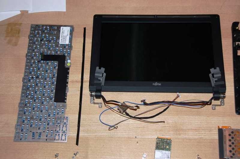
23) Closeup of the keyboard and display:
24) Reassembly is nearly as simple as reversing the steps, assuming you kept track of which screws
go where. The connectors are fairly simple, but quite delicate. Be especially careful of the flat-cable
sockets, which require a firm push in a straight line. Take your time and don't wiggle or crimp them!
When done, it is very important to stick the keyboard down well. If the old glue is hardened or
damaged, you'll get a lot of flex in the keys and it will drive you crazy. I used a removable
gluestrip applicator which I found in a crafts store in the photo/scrapbooking section. There are
also permanent glues - not recommended.

That's about it! I didn't dismantle the screen assembly, sorry. It seems fairly straightforward,
I suspect there are screws under the two square covers near the hinges, and possibly two more at
the top below the rubber bumpers. Let me know if you've been into that assembly.
Tom. |
|
|
MarkieMark
Starting Member
USA
10 Posts |
Posted - 05/28/2009 : 00:53:10
|
Thanks, that is very helpful.
Any idea of which step one could stop at to repair the dc jack?
Thanks,
Mark |
 |
|
|
tmt
Advanced Member
2766 Posts |
Posted - 05/28/2009 : 09:31:40
|
Once the top cover is off, the DC jack is exposed and lifts out easily. you can see it
in photo 9at the upper right, and a closeup at photo 14. It plugs into the top right
corner of the motherboard with two wires threading through the plastic tunnel. Simple.
Tom. |
|
|
|
MarkieMark
Starting Member
USA
10 Posts |
Posted - 05/28/2009 : 09:36:05
|
Perfect, thanks again for the pictures. I'll give it a go this weekend hopefully.
Mark |
|
|
|
oion
Advanced Member
USA
2231 Posts |
Posted - 06/14/2009 : 10:45:59

|
Thanks for this, Tom. I'll be archiving this thread offline because I'm sure I'll crack this puppy open when it's a bit more worn out. 
This P-7230 keyboard is absolutely not as durable as my ol' P-2040's. While pressing some clear keycap stickers into it, I must have pressed too hard in the upper left and the dang keyboard now squeaks and clicks when I press the keys around "1." Very annoying. I really miss my P-2k's tactile response. But I digress... |
|
|
|
journey
Starting Member
3 Posts |
Posted - 07/10/2009 : 00:12:25
|
This is very good information, Tom. Thanks a lot.
I've a p7230, but is died. Cannot even power up, i.e. nothing happen when I press on the power button. I'll open up to check this weekend. Do you happen to know what should I check or pay attention to? Many thanks in advance. |
|
|
|
tmt
Advanced Member
2766 Posts |
Posted - 07/10/2009 : 01:01:08
|
If the blue light in the power button doesn't light, then definitely check for a bad
power supply or broken power connection. Remove the battery and try with AC, or remove
the AC and try with the battery.
If the blue light does light, then are there any beeps and/or does the fan come on?
Have you changed any hardware lately? Focus on what's new if so.
Sorry, I don't have any magic debugging suggestions.
Tom. |
|
|
|
journey
Starting Member
3 Posts |
Posted - 07/10/2009 : 02:46:54
|
quote:
Originally posted by tmt
If the blue light in the power button doesn't light, then definitely check for a bad
power supply or broken power connection.
Thanks a lot. Will check them out.
quote:
Remove the battery and try with AC, or remove
the AC and try with the battery.
Tried that, both don't work, no blue light at all.
quote:
If the blue light does light, then are there any beeps and/or does the fan come on?
Have you changed any hardware lately? Focus on what's new if so.
Nothing added. Just died one day... after a month or so unused. Many thanks again. |
|
|
|
tmt
Advanced Member
2766 Posts |
Posted - 07/10/2009 : 21:20:11
|
quote:
Originally posted by journey
after a month or so unused. Many thanks again.
Check your internal battery (the yellow-wrapped CMOS one stuck to the motherboard). If
it dies, perhaps the power energizing circuit does too. My older Sonys always used to
do that. I would have to plug them in for several hours before they would charge or
power up. I've never had my Fujitsu do this, however.
One other possibility comes to mind. The power button connects to the motherboard
via a flat cable, labelled "1" in the photo below and the one I wrapped a pencil around
to remove. If this cable comes loose, the power button will be completely disconnected.
Seems very unlikely, however.
Tom. |
|
|
|
journey
Starting Member
3 Posts |
Posted - 07/12/2009 : 21:27:23
|
quote:
Originally posted by tmt
Check your internal battery (the yellow-wrapped CMOS one stuck to the motherboard). If it dies, perhaps the power energizing circuit does too. My older Sonys always used to do that. I would have to plug them in for several hours before they would charge or power up. I've never had my Fujitsu do this, however.
Checked the voltage of the battery, and realised it is zero, and replaced the battery. But still unable to power up.
quote:
One other possibility comes to mind. The power button connects to the motherboard via a flat cable, labelled "1" in the photo below and the one I wrapped a pencil around to remove. If this cable comes loose, the power button will be completely disconnected. Seems very unlikely, however.
The cable is the first I checked. I even checked for connectivity of the cable using a multi-meter.
Do you have anymore suggestion, else I guess I've to let it RIP...
Thank you once again. |
|
|
|
tmt
Advanced Member
2766 Posts |
Posted - 07/13/2009 : 10:37:40
|
That would be a real shame! But it sounds like it needs a trip to the Fujitsu repair depot,
and that might be expensive. I would give them a call, at least, to see if there's a flat
rate. Probably it beats ending up settling for a netbook downgrade!
Tom. |
|
|
|
rahrahrachel
Junior Member

United Kingdom
130 Posts |
Posted - 09/08/2009 : 14:59:11
|
Thank you so much for this. First time round i tried i broke the keyboard holder. This time though i had no problems.
I followed your instructions to a T.
I thought that we might have different designed computers but that is not really the case. My niece owns a pink P7230.
I had to open it to change the thermal paste. The laptop was idling in the mid 70s and hitting the 80s without much stress.
I changed the thermal paste to ICD7.
Now this means that i don't need to send this to the repair centre for the probably 5+ time.
Sony SZ71WN/C 2.5, 4GB, 128GB SSD
Sony TX5XN/B 1.33 core solo, 2GB, downgrade XP, 64GB SSD SLC.
|
Edited by - rahrahrachel on 09/09/2009 03:17:38 |
|
|
|
rahrahrachel
Junior Member
United Kingdom
130 Posts |
Posted - 01/20/2010 : 10:17:23
|
I need to take the display housing of. Does anyone has any idea how i would do that? I need to just swap the housing and leave the display. With my TX there were clips that i needed to prise apart but i cannot seem to locate them with this laptop.
Edited to add:
I figured it out, those two circular things that protect the display that is on the bezel you have to remove them. Underneath there are two screws. Then you have to prise the display apart very gently. Also, at the bottom there are two small square boxes and you have to remove them also. You should start at the top at try and pry it of gently. Again there are two screws there also.
Sony SZ71WN/C 2.5, 4GB, 128GB SSD
Sony TT SU9600 White, 4GB DDR3,128GB SSD, WWAN, HDMI.
|
Edited by - rahrahrachel on 01/20/2010 12:48:55 |
|
|
|
tmt
Advanced Member
2766 Posts |
Posted - 01/20/2010 : 23:58:24
|
So, do I understand correctly - there are 4 screws: two beneath the rubber bumpers and
two more beneath the little squares?
Tom. |
|
|
|
rahrahrachel
Junior Member
United Kingdom
130 Posts |
Posted - 01/21/2010 : 06:59:03
|
That is correct tmt.
Sony SZ71WN/C 2.5, 4GB, 128GB SSD
Sony TT SU9600 White, 4GB DDR3,128GB SSD, WWAN, HDMI.
|
|
|
| |
Topic |
|
|
|
